
Research Signal – Source date 2021-10-11
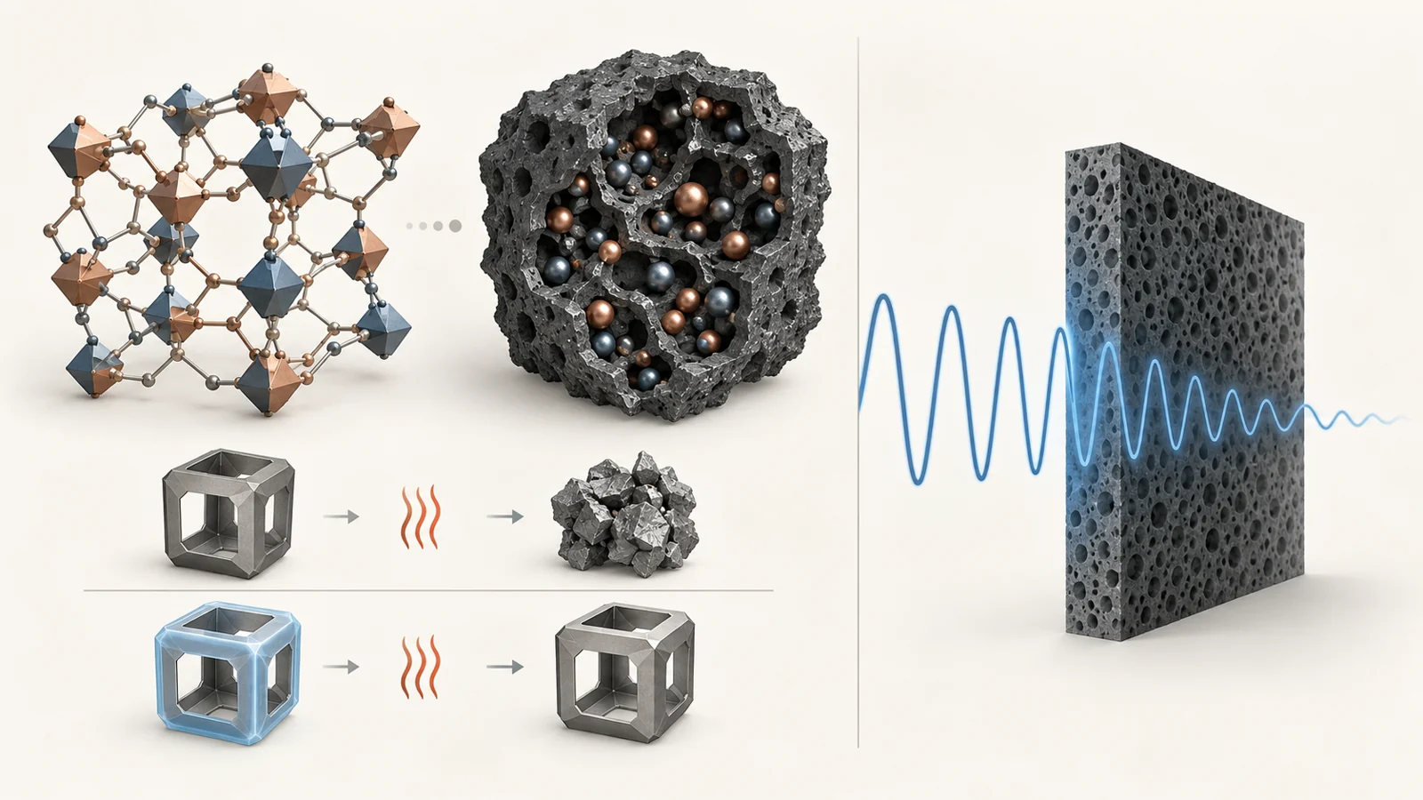
A tiny hollow box can be carefully built, then lose its shape during the heating step that gives it useful properties. That happened in one example described in a review published on October 11, 2021. Researchers made hollow nickel–cobalt precursor boxes, but heating left them as clumps of particles. Adding a resin coating before heating helped the boxes keep their hollow structure—and changed the material they became.
The starting materials belong to a family called metal–organic frameworks, or MOFs. These are porous crystalline structures built from metal sites connected by organic molecules. Heating suitable frameworks in an inert atmosphere converts their organic components into carbon and can turn their metal sites into magnetic particles dispersed through that carbon. The original scaffold is consumed in making the absorber.
The review examines how changing the ingredients and preserving selected shapes can improve microwave absorption. Its examples also explain why an impressive absorption number cannot identify a universally useful material. A candidate must work at relevant frequencies, at an acceptable thickness and material loading. Before any of that, an incoming wave must actually enter it.
Getting a wave inside is only part of the job
Microwaves have electric and magnetic fields. A composite containing carbon and magnetic particles offers ways to interact with both. But the ability to dissipate energy inside a material matters only to the extent that the wave reaches that interior. A material can have strong internal losses while reflecting too much energy at its surface.
This is the practical meaning of impedance matching. The absorber’s electromagnetic response must allow a favorable transition from the surrounding space into the material. A large mismatch encourages reflection. Once the wave enters, attenuation describes how its energy diminishes within the absorber. Entry and dissipation are separate requirements, so simply increasing a material’s capacity for internal loss does not guarantee better absorption.
The carbon contributes to electrical losses. The wave’s electric field drives charge movement, which can dissipate energy. Energy can also be lost as electric dipoles respond with a delay to the changing field. Boundaries between different components provide another opportunity: charges can accumulate unevenly at these interfaces, contributing to polarization loss. The distribution of carbon, particles and their contact surfaces therefore matters alongside the amount of each ingredient.
Magnetic particles supply additional loss mechanisms associated with their response to the magnetic field, including magnetic resonance and circulating electrical currents. In the composites discussed by the authors, the electrical response is often much larger than the magnetic response. Increasing conductivity alone can therefore strengthen one loss mechanism without producing the conditions needed for waves to enter effectively.
Changing the metal also changes the carbon
A framework offers an orderly starting arrangement of metal sites and organic molecules, which can help distribute magnetic particles through the resulting carbon. Its recipe also imposes constraints. Each type of precursor has a characteristic relationship between its metal sites and organic components; heating that precursor does not automatically produce the most useful final proportions or properties.
An iron–cobalt example in the review shows how much can change when researchers adjust a metal ratio. Precursors containing iron and cobalt were heated to make iron–cobalt alloy particles in carbon. A small cobalt addition, at a cobalt-to-iron atomic ratio of 0.1, suppressed the formation of iron carbide, a competing phase that the authors associate with a weaker magnetic response in this system.
Cobalt also promoted graphitization more effectively than iron. Graphitization describes the development of more ordered, graphite-like carbon, so changing the metal mixture altered the surrounding carbon as well as the magnetic particles. The addition of cobalt also reduced the average particle size, creating more interfaces where charge accumulation could contribute to energy loss.
A metal ratio is thus a way of changing several features at once: which phases form, how the carbon develops, and how much boundary area exists between components. The example gives a concrete reason to investigate mixed-metal precursors. It does not supply a simple rule that more cobalt always produces a better absorber.
A hollow precursor has to survive the furnace
The nickel–cobalt boxes illustrate a different challenge. Researchers used ammonia etching to create hollow precursor boxes with truncated corners. Those shapes existed before the high-temperature conversion. After heating, however, the hollow architecture disappeared and the final nickel–cobalt/carbon material consisted of agglomerated nanoparticles.
Coating the etched boxes with phenolic resin before heating changed the outcome. The coating helped reinforce the structure so that the final composite retained its hollow form. According to the review, the resulting hollow material showed better microwave absorption than the particle agglomerates.
That sequence makes the manufacturing problem visible. Designing a hollow precursor and obtaining a hollow absorber are distinct achievements. An attractive starting shape has little value if the conversion step destroys it. The coating provided a way to carry the intended architecture through that step.
The comparison also has a limit that affects its interpretation. The resin changed the final chemical composition while helping preserve the hollow structure. Its benefit cannot be assigned to geometry alone. A photograph of an intact box establishes that the shape survived; understanding the absorption improvement also requires accounting for the material introduced by its support layer.
What the absorption numbers actually describe
The review compares materials using reflection loss and effective absorption bandwidth. Reflection loss, expressed in decibels, describes how much of the incoming wave is reflected under specified conditions. More negative values mean less reflection. In the metal-backed absorber configuration used for the review’s calculations, a value of −10 dB corresponds to 90% of the incident energy being absorbed, because the backing prevents transmission through the layer.
Effective absorption bandwidth is the frequency interval over which reflection loss stays at or below that −10 dB threshold. It answers a different question from the deepest reflection-loss minimum. The minimum describes the strongest result at a particular frequency; the bandwidth describes how broadly the material meets the chosen absorption threshold at a specified thickness.
Two entries from the review’s comparison table make the distinction clear. These are results reported by the review from earlier studies, rather than materials tested against each other under one common protocol.
Material described in the review Deepest reflection-loss minimum Effective absorption bandwidth Filler loading by weight Hollow cobalt/carbon cage −60.6 dB at 9.8 GHz, with a 2.4 mm layer 5.1 GHz, covering 10.8–15.9 GHz, with a 1.9 mm layer 10% Hollow iron–cobalt/carbon cage −67.8 dB at 5.3 GHz, with a 1.7 mm layer 5.3 GHz, covering 11.0–16.3 GHz, with a 2.0 mm layer 50%
In each row, the thickness associated with the deepest minimum differs from the thickness associated with the listed bandwidth. Combining those values into one description of a single layer would create a performance claim that the table does not make. Thickness helps determine the electromagnetic response of the complete layer; it is part of the result, not merely a packaging detail.
The iron–cobalt entry has the deeper minimum and reaches it at a lower frequency. The cobalt/carbon entry uses a much lower filler loading. Neither fact settles which would be useful in a particular component. Filler loading is the share of absorber material by weight in the tested mixture, not a measurement of a finished component’s weight, durability, cost or ease of manufacture.
These figures are useful because they connect performance to conditions. They become misleading when reduced to a contest over the most negative decibel value.
The frequency gap matters for electronics
The iron–cobalt cage’s minimum at 5.3 GHz is a useful exception to a broad concern raised by the authors. They report that many optimized magnetic carbon composites are mainly effective in the 8–18 GHz range, while many electronic devices operate below 8 GHz. Strong absorption outside the frequencies relevant to an application cannot solve that application’s interference problem.
A lower-frequency minimum does not by itself close the gap. In the iron–cobalt example, the listed broad absorption interval is 11.0–16.3 GHz, measured at a different thickness from the minimum. A deep point at 5.3 GHz therefore does not establish broad useful coverage below 8 GHz. Frequency coverage has to be read directly rather than inferred from the best point on a curve.
Fabrication adds a separate obstacle. Etching, templates and protective coatings can create or preserve useful structures, but they also introduce multiple processing steps. The authors identify simpler preparation as an important unresolved need. The coated boxes show why this is a substantive challenge: removing a step for convenience could also remove the feature that allowed the hollow structure to survive.
From the review’s 2021 perspective, the materials offer promising ways to control absorption, while the route to a practical absorbing layer remains conditional. Laboratory performance at selected frequencies and thicknesses does not establish interference reduction in operating equipment or commercial readiness.
What this could change
If these composites can absorb across frequencies relevant to electronic equipment, meet thickness and loading requirements, and be made through simpler processes, equipment designers could gain useful absorbing layers for reducing unwanted microwave reflections and interference. Magnetic particles and carbon would provide complementary ways to dissipate incoming energy, while a structure that survives fabrication would make the intended material properties available in the finished layer.
The downstream value would be the ability to fit effective absorption into the space and material budget of equipment that needs it. Achieving that capability depends on carrying the promising material behavior beyond a deep absorption minimum into the frequency coverage and fabrication conditions a real component requires.
Key Sources
- Primary source: Composition Optimization and Microstructure Design in MOFs-Derived Magnetic Carbon-Based Microwave Absorbers: A Review.
DOI or Journal Page · Peer-Reviewed Paper · 2021-10-11
Keep exploring