
Research Signal – Source date 2025-07-02
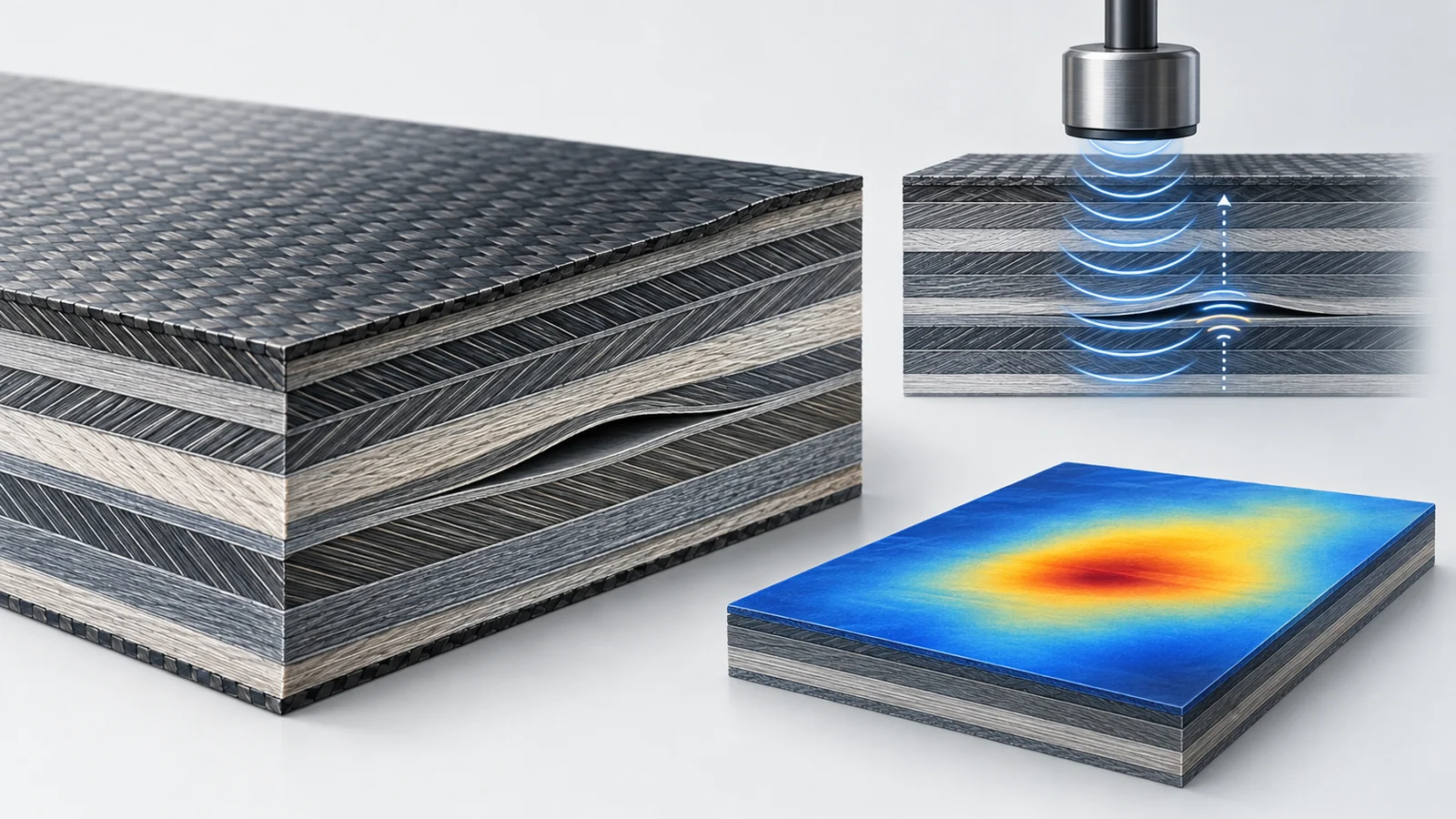
A split between the layers of a fibre-reinforced aircraft part can be hidden from view while the outer surface still looks intact. Inspectors need ways to examine the inside without cutting the part open. A review published July 2, 2025, surveyed 120 articles on non-destructive testing of composite materials published from 2015 to 2025. It found ultrasonic testing to be the most frequently studied approach, while also showing why a second kind of scan may help make sense of damage.
The review brings together methods used to look for defects such as delamination, where layers separate, as well as debonding and voids. It describes research priorities and examples of how different scans have been applied. Its article counts show what researchers studied, not how likely a method is to find damage in any particular aircraft part.
Sound travels differently through layered material
Ultrasonic testing sends sound waves through a material and interprets the returning signals. The review reports that ultrasound appeared in about 45% of the articles it examined. Researchers use it to look for subsurface defects, including delamination, disbonding and porosity.
The method’s popularity does not make every reading straightforward. Fibre-reinforced composites are anisotropic: their properties vary with direction. As a result, sound can travel at different speeds and lose energy differently depending on the direction of the fibres. This can affect the signal and the detail an inspector can resolve, especially in thick sections. It also makes it harder to choose a reference block for calibrating a test.
Frequency adds another trade-off. Higher-frequency ultrasound can reveal finer features near the surface, but it penetrates less deeply. The review describes frequencies of 10–25 MHz as useful for resolving small defects such as delamination, fibre waviness and microcracks near the surface. That detail may come at the expense of seeing farther into a thick or layered part. The direction of the fibres and the depth of the suspected defect therefore matter when interpreting a scan.
Phased-array ultrasonic testing, which the review reports in 20% of the articles, was discussed as an approach offering greater sensitivity, flexible imaging and faster scanning than conventional ultrasound. That share is also a share of reviewed articles; it is not a head-to-head measure of how often phased arrays find a defect.
A second view can add different information
A scan records how a material responds to a particular inspection method. A second method can provide a complementary view, helping researchers characterize damage that may be difficult to interpret from one set of signals alone.
The review describes prior work that combined ultrasonic imaging with thermography, the use of heat-related patterns to inspect a material. That work examined delamination, impact damage and porosity. The review presents the combination as a way to characterize a wider range of defects than either method alone. It is an example reported in the reviewed literature, not a new combined system tested by the review itself, and the supplied evidence does not give a quantified performance comparison for a maintenance setting.
The value of using two methods depends on what each can reveal in the part being inspected. A result that appears ambiguous in one view might be checked against a different physical view. For aircraft maintenance, that could help an inspector decide whether a location needs closer investigation. The review’s synthesis, however, does not establish a validated procedure for making that decision across aircraft parts and defect types.
Internal detail has practical limits
X-ray computed tomography creates images of a specimen’s internal structure. The review describes its use to examine void content in fibre-reinforced composites, drilled holes in carbon-fibre composites, and internal damage in sandwich structures after low-velocity impacts. Digital radiography and tomography have also been used to detect debonding, delamination and voids in carbon-fibre specimens. The review notes that digital radiography is relatively low-cost compared with tomography, while the size of tomography equipment can limit the size of specimen examined.
Those examples show why a highly detailed internal image does not automatically make a method the routine choice for every part. The specimen must fit the equipment, and the inspection must suit the material and the question being asked. A research specimen that can be examined in a tomography machine is not necessarily evidence that the same approach can be used on a full-size component in its service setting.
What 120 articles can tell us
The 120-article synthesis can show which methods appeared most often in the literature it reviewed, what kinds of defects researchers examined, and where the review identifies opportunities or obstacles. It reports that ultrasound dominated the articles, with thermography and other methods also represented. These frequencies describe research attention within that set of articles. They are not detection rates, nor do they show that the most frequently studied method is best for a particular material, defect, depth or testing condition.
Comparisons are complicated by differences in fibre direction, thickness, specimen size and the defects under examination. The review emphasizes that method choice depends on material properties, defect type and testing conditions. It also identifies gaps in standardization and certification for advanced inspection methods. Without consistent ways to validate and interpret results, promising combinations may be difficult to compare or apply reliably across settings.
What this could make possible
A dependable combination of scans could help an aircraft-maintenance inspector check an unclear indication from more than one angle before deciding where to investigate. The ingredients are already present in the reviewed literature: ultrasound is widely studied, thermography offers a complementary view, and prior work has combined ultrasonic imaging with thermal analysis. What remains a prospect is a standardized, validated way to interpret those signals together for relevant parts and defects. The review points to standardization and certification as gaps, and it does not establish routine use or quantified outcomes for this maintenance scenario.
A nearer milestone would be a replicated comparison of combined and individual scans on the same composite specimens with known defects. Reporting missed and false indications across different fibre directions and thicknesses could show where the combined view adds dependable information. If that evidence supported consistent interpretation and the approach could be validated for the parts in question, inspectors might have a stronger basis for deciding when an apparent split merits further investigation. That practical capability depends on validation still to come; the review describes the research direction, not a finished inspection system.
Key Sources
- Primary source: Recent Trends in Non-Destructive Testing Approaches for Composite Materials: A Review of Successful Implementations.
DOI or Journal Page · Review or Meta-Analysis · 2025-07-02
Keep exploring