
Research Signal – Source date 2025-12-29
A radar-absorbing panel has to solve two problems at once: let electromagnetic waves enter, then dissipate their energy without adding too much thickness or weight. A panel intended for an aircraft surface also needs to contribute structural support. Those goals can pull in different directions, since a more mechanically robust design may be harder to tune for broad absorption.
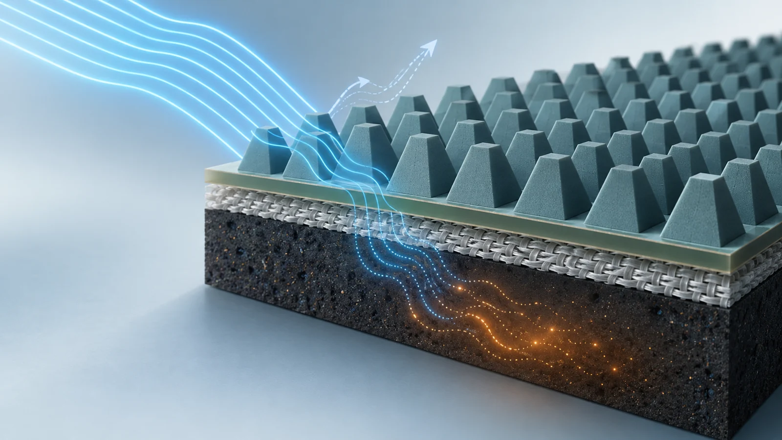
A 2025 materials study explored that challenge with a fabricated composite plate built from several layers and a repeating tapered surface. The authors report a broad absorption range and describe the design as fiber-reinforced. The evidence has several routes, though: chamber measurements cover one frequency range, while simulations examine higher frequencies and radar-cross-section behavior. The reported broadest span should be read in that context.
Each layer has a different job
The design combines a wave-transmitting FR4 layer, a shaped dielectric region, a magnetic skin, and fiberglass cloth. The FR4 layer is meant to help incoming waves enter the structure. This first step matters because a wave reflected at the surface cannot travel through the absorber to lose energy inside it.
Within the dielectric region, repeated tapered units create a gradual change in geometry. The authors describe the shape as supporting impedance matching—the alignment between the panel and the wave that makes entry easier—and multiple internal reflections. A wave can therefore travel through a longer, less direct path within the structure before leaving it.
The magnetic region supplies a different part of the process: energy dissipation through magnetic loss. The material recipe also varies across the panel. The concentration of carbon nanotubes in the dielectric layer rises from the outside inward, while the concentration of carbonyl iron particles in the magnetic skin falls from bottom to top. In the authors’ design, these composition gradients work alongside the geometric gradient to balance entry and loss.
Fiberglass cloth is embedded as a support layer. It reinforces the layered structure and helps maintain its form, while the absorbing adhesive is applied over it. These roles make the panel a composite design rather than a single lossy material shaped into a slab.
The shape changes the frequency response
The repeating units use a hexagonal arrangement, with truncated-pyramid shapes whose widths narrow toward the top. Their sloping sides are intended to guide waves through multiple reflections. The team compared different proportions of the shaped dielectric region and magnetic skin, as well as variations in the prism angle.
Those comparisons show why adding absorbing material alone is not enough. A thicker magnetic skin paired with a thinner shaped region shifted absorption peaks toward lower frequencies and made high-frequency matching poorer in some configurations. Increasing the shaped region relative to the skin improved high-frequency alignment in other samples. But making that region excessively thick also reduced wave transmission and worsened matching.
The selected 70-degree geometry reduced the structure’s volume relative to a full-thickness layer while broadening the effective absorption bandwidth in the reported analysis. The authors attribute its performance partly to the sloped surfaces, which give obliquely arriving waves more opportunities to reflect within the structure. The results point to a tuning problem involving the order and proportions of layers, not simply the quantity of magnetic or conductive ingredients.
What the chamber measurements cover
The researchers fabricated a composite plate measuring 200 by 200 millimeters and 3 millimeters thick. They measured reflection loss in a microwave anechoic chamber using an arch method, with tests described over 2–18 GHz. Reflection loss indicates how much of the incident microwave energy is reflected; lower reflection is consistent with more energy entering and being absorbed by the sample.
The paper reports an effective absorption span of 8.6–26.4 GHz across the X, Ku, and K bands. That headline range extends beyond the described chamber measurement window. The paper also compares variants with different FR4 layer thicknesses in simulations; one configuration, N5, is reported with a 17.8 GHz effective absorption bandwidth and two absorption peaks. The broader 8.6–26.4 GHz claim should therefore not be read as a chamber measurement across every frequency in that span.
The source describes a total thickness of 3.5 millimeters and an effective thickness of 2 millimeters for the proposed absorber. These figures sit alongside the separate account of a fabricated 3-millimeter plate, and the available descriptions do not resolve them into one universal thickness specification. The study also reports a density about one-third that of conventional magnetic metamaterials, but that comparison does not substitute for a quantified structural test.
Direction matters for a shaped absorber
A panel may meet waves at different angles and with different polarization—the orientation of the wave’s electric field. Both can affect how a shaped structure couples to an incoming wave. The authors attribute polarization insensitivity to the absorber’s fourfold rotational symmetry and report stable response up to 60 degrees, particularly under transverse-electric polarization. The stated angle performance is thus tied to the reported polarization context.
The paper also presents radar-cross-section simulations, including a reported reduction of 15 dB at 22.4 GHz. Radar cross-section describes how strongly an object reflects radar energy in a modeled setup. Such results can help assess a design, but they do not show whether an aircraft would be detected in operating conditions. No field performance should be inferred from these calculations alone.
Fiberglass supports the design, but strength remains unquantified
The fabrication route builds the shaped region in a mold, places fiber cloth into the layered structure, and applies magnetic absorbing adhesive over it. The polyurethane mixtures containing carbon nanotubes or carbonyl iron are dispersed with stirring and ultrasonication, then cured at room temperature. The authors describe the process as relatively complex.
That detail matters to the proposed structural role. The fiber cloth is intended to reinforce the panel and support its layered architecture, while the absorbing coating provides the magnetic function. The study presents this combination as a way to address the usual tension between broad electromagnetic absorption and mechanical robustness. The supplied results describe the construction and electromagnetic tests, but do not provide a quantified load-bearing result or qualify the material as an aircraft structure.
What this could mean for aircraft surfaces
A lightweight exterior panel that absorbs radar waves across a broad frequency range while contributing structural support could give aircraft designers another way to integrate those functions. This study offers a fabricated material design and evidence of microwave absorption, but that capability depends on reproducible measurements across the full claimed range, quantified mechanical performance, and validation under operating conditions. Until then, aircraft use remains a possibility proposed by the authors rather than a demonstrated deployment.
Key Sources
- Primary source: Magnetoresponsive Fiber-Reinforced Periodic Impedance-Gradient Absorber: Design and Microwave Absorption Performance.
DOI or Journal Page · Peer-Reviewed Paper · 2025-12-29
Keep exploring