
Research Signal – Source date 2021-02-02
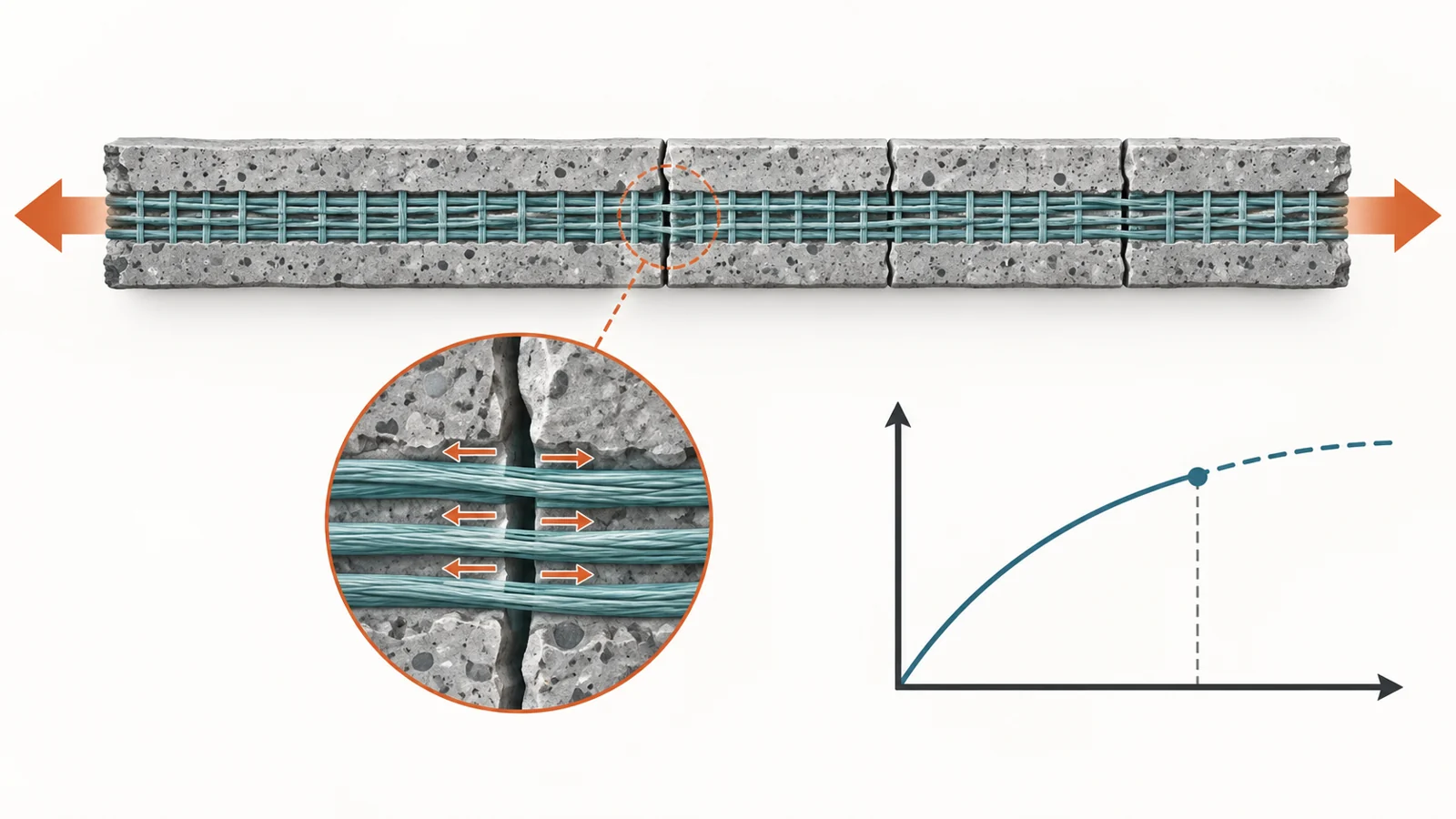
A crack in mortar does not necessarily end its ability to carry a pulling force. When fabric mesh is embedded inside it, the fibers can bridge the opening and continue carrying load. This combination, called textile-reinforced mortar, is used to strengthen existing masonry. But predicting when the mortar first cracks is only part of describing its behavior. A model can reproduce that opening stage yet credit the composite with more stretching afterward than a specimen actually achieves.
A February 2021 review with an experimental investigation examines this problem by comparing three existing analytical models with published tensile tests and new tests on glass-mesh mortar strips. Its most revealing comparison concerns where the predicted response ends. Stopping theoretical curves at the measured failure strain substantially improves agreement with experiments—but that measured endpoint supplies information the model would otherwise have to predict.
What happens between the first crack and failure
The familiar three-stage response begins with intact mortar. At this point, the mortar largely determines how strongly the strip resists stretching. On a graph of pulling force against strain—the extension relative to the length being measured—the response rises along an approximately straight line. Its slope describes stiffness: a steeper line means that more force is needed for an additional amount of stretching.
Once the first crack forms, the response changes. Further cracks develop, and the strip becomes less stiff. The fabric and mortar must transfer force between them through their shared interface. How well they remain bonded helps determine how cracking spreads and how the composite continues to carry load.
After the crack pattern stabilizes, the fabric chiefly governs the final rising part of the curve. Fibers bridge the separated mortar, and their mechanical properties largely determine the slope. This produces the three approximately straight segments that engineers often use to simplify a complicated physical process.
That sequence depends on effective load transfer. If fibers slide within the mortar, slipping can interrupt the development of the fabric-dominated stage and bring failure earlier. Some responses therefore resemble two segments rather than three. The mesh and mortar cannot be understood simply by adding together their separate strengths; their connection helps determine which properties the combined strip can mobilize.
Three ways to represent the connection
The paper examines the Aveston–Cooper–Kelly model, usually shortened to ACK; the Simplified Model proposed by Minafò and La Mendola; and the Tension Stiffening Model. These are alternative mathematical descriptions of tensile behavior, intended to be easier to use than detailed numerical simulations of the composite’s internal structure.
A useful distinction is how they handle the bond between fabric and mortar. The Tension Stiffening Model includes a coefficient that explicitly represents the influence of that bond. ACK and the Simplified Model incorporate bond effects indirectly through empirical calibration against experimental results. Their equations therefore carry information about the bond conditions in the tests used to develop them, without representing that influence in the same explicit way.
This matters when moving between materials. A relationship calibrated on one collection of tests may describe the average behavior there, while responding less well to a fabric or treatment with different slipping characteristics. An explicit bond coefficient provides a way to represent that difference, although its usefulness still depends on how well the model matches the material being tested.
The grips become part of the experiment
The new investigation used seven glass-textile mortar strips cut from two separately manufactured panels. Each strip was 60 millimeters wide, 400 millimeters long and 8 millimeters thick. The mesh sat between two mortar layers, with an adhesion promoter at the fabric–mortar interfaces. Additional fabric reinforced the panel ends to help prevent premature failure where the testing machine would grip the specimens. The panels cured for 28 days before cutting.
Despite those precautions, the two groups behaved differently. The two specimens designated TRM-1 developed cracks along their lengths, together with slipping and fiber rupture. The five TRM-2 specimens reached lower strengths and failed around the clamping zones, with more pronounced slipping.
The authors suggested that inefficient bonding of the end tabs could have contributed to slipping at the grips. They also proposed differences in manufacturing and a slightly different mortar composition as possible explanations for the contrast between the panels. These were tentative explanations, rather than separately demonstrated causes. Because of the experimental problems, all five TRM-2 specimens were excluded from the subsequent database and model assessment. The retained new evidence therefore came from the two TRM-1 specimens, alongside the literature results.
The broader comparison shows why specimen handling deserves this attention. In a clevis-grip arrangement, glued metal plates connect the strip to the machine through pins. Force passes through the fabric–mortar interface, and slipping can cause failure before the fibers reach their tensile strength. In direct clamping, lateral pressure at the ends limits that slipping and more often allows the three-stage response to develop.
Clamping still does not guarantee a clean measurement of the intended material behavior, as the TRM-2 results illustrate. The way force enters a specimen can influence both the shape of its curve and where it fails. A model comparison consequently tests more than the names of the ingredients—it also depends on how the experiment allows those ingredients to work together.
Why the endpoint changes the energy comparison
To compare whole portions of the response rather than isolated points, the researchers calculated an area-based post-cracking energy metric. It comes from the area under the tensile response curve after cracking begins. The area depends on both the load carried and the range of strain over which the specimen continues carrying it.
This makes the metric sensitive to excessive predicted stretching. A theoretical curve that continues beyond the specimen’s actual failure accumulates additional area. Across the comparisons, complete model curves could substantially overestimate the experimental metric; the Simplified Model’s estimate reached up to 14 times the experimental value. That figure describes a discrepancy in this specimen-level comparison, not a multiplier for building safety or strengthening performance.
The authors then repeated the calculation after cutting each theoretical curve off at the experimentally measured ultimate strain. In ordinary terms, they stopped counting the prediction when the corresponding test specimen had reached its measured limit. The average overestimates then fell to:
- 31% for ACK
- 57% for the Simplified Model
- 15% for the Tension Stiffening Model
The Tension Stiffening Model produced the smallest errors in the reported energy comparison. The remaining differences also show that supplying the endpoint does not make the predicted curve identical to the observed one.
There are two different questions here. One is how well a model describes the response over the strain range the specimen survived. The other is whether it can determine that range independently. Cutting the curve at measured failure helps answer the first question by borrowing the endpoint from the experiment. Improved agreement under that condition does not establish that the model can predict failure strain on its own.
Agreement depends on what is measured
The retained glass-mesh specimens provided a useful example of closer agreement. The models reproduced the initial stage well and predicted the slope of the final stage reasonably well. ACK and Tension Stiffening also closely predicted ultimate elongation in those tests. Strain was recorded with an internal transducer that measured deformation locally, which the authors identified as a contributor to the more reliable comparison.
Across the literature database, however, measurement arrangements varied, as did fabric type, fiber treatment, mortar properties and gripping method. The review considered carbon, basalt and glass fabrics. Its dispersed results and limited repeatability make it difficult to transfer one apparent model success to all of those combinations. The better energy results for Tension Stiffening support its performance in this comparison, rather than establishing a universally best choice.
The loading itself sets another boundary. These experiments concerned uniaxial tension: pulling along one direction. Under stresses acting in two or three directions, the pattern of cracking and the geometry of the mesh could play different roles. The authors identified those conditions as requiring further investigation. A model suitable for a pulled strip therefore still needs evidence connecting it to the more complicated conditions relevant to a strengthening application.
What this could change
If simple tensile models can become transferable across relevant fabrics, mortars and loading conditions, engineers could use them to design masonry strengthening with a more realistic account of how force passes from cracked mortar into the mesh. That would make it easier to relate the chosen composite’s properties to the response an intervention is intended to provide.
The prospective benefit is a more usable design basis for strengthening existing masonry with compatible materials. Inorganic mortar systems are attractive partly because of their compatibility and breathability on masonry supports. Better descriptions of their behavior could help engineers make practical use of those qualities while accounting for the bond and deformation that govern load sharing. From the February 2021 evidence, that remains a conditional design capability, supported by a clearer understanding of where the existing models succeed and where experiments still supply essential information.
Key Sources
- Primary source: Constitutive Models for the Tensile Behaviour of TRM Materials: Literature Review and Experimental Verification.
DOI or Journal Page · Review or Meta-Analysis · 2021-02-02
Keep exploring