
Research Signal – Source date 2021-02-18
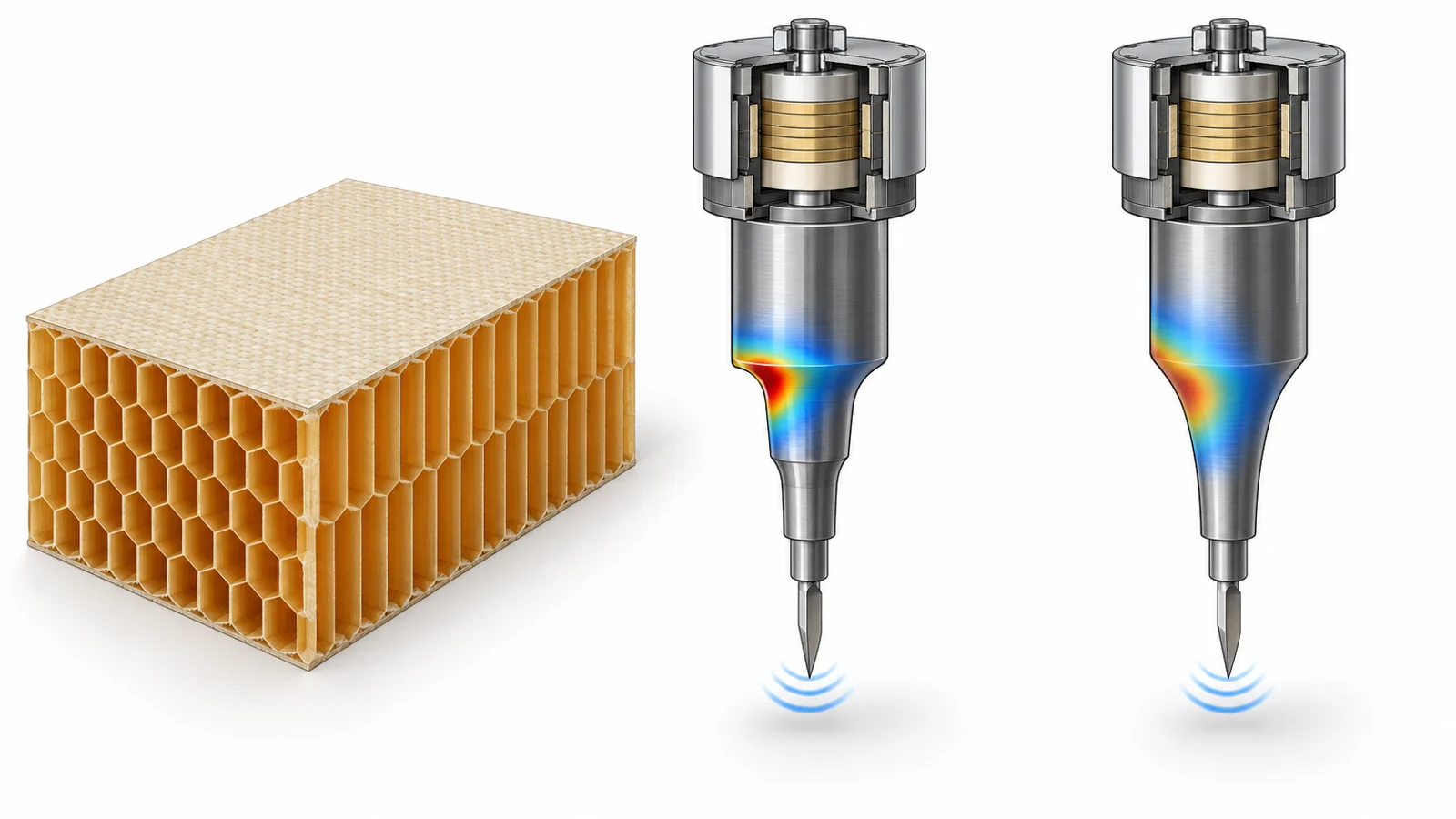
Fragile Nomex honeycomb can be damaged by conventional cutting, so a tool that vibrates as it cuts may help machine the material. But the part that amplifies that vibration faces a design tradeoff: a horn that produces more motion at the tool can also concentrate more stress in the horn itself.
A 2021 preprint compared many horn shapes in computer models to examine that tradeoff. Its results suggest why choosing a design by vibration amplitude alone could be misleading—and why some less dramatic shapes may make better candidates for further testing.
The small motion that the horn must amplify
In ultrasonic vibration-assisted machining, an electrical generator supplies a high-frequency signal to a transducer, which turns it into mechanical vibration. The transducer’s motion is small: the study used an input amplitude of 5 micrometres. A mechanical horn sits between the transducer and the cutting tool, increasing the vibration reaching the tool end.
That amplification matters because the tool is meant to vibrate while machining a soft, brittle composite. Yet the horn also has to withstand repeated motion at high frequency. The authors note that high operating frequencies can expose horns to stresses that may lead to failure. The design problem is therefore not simply to maximize movement at the tip; it is to gain useful movement without creating an unfavorable stress pattern in the horn.
A controlled comparison of different shapes
To compare geometries, the researchers modeled horns with the same material, length, and diameters at the transducer and tool ends. Each horn was 114 millimetres long, with a 41-millimetre diameter at the transducer side and a 33-millimetre diameter at the tool end. The material was mild steel. The modeled operating frequency was 20 kilohertz, with the transducer end moving at 5 micrometres.
Keeping these inputs alike made the shape comparison more meaningful: differences in the modeled results could be compared under common conditions. The researchers used finite-element analysis, a way of estimating how a designed object responds by representing it as many connected regions in a computer model.
One calculation estimated the frequencies at which each horn would vibrate along its length; another estimated how much it moved and where stress built up when driven. The researchers also calculated a factor of safety, a margin against failure under the model’s assumptions, and compared predicted operating life. These are numerical comparisons for the modeled setup, not tests of horns cutting honeycomb.
More amplitude came with a stress tradeoff
The barrel horn was reported as the highest-amplification design among those considered. The abstract also says barrel, cylindrical-double-conical and hollow-exponential horns achieved greater axial modal frequencies and vibration amplitudes than the step horn. Those higher values did not make them straightforward winners: the same group was prone to greater stress concentrations and shorter predicted operating life.
A stress concentration is a region where stress builds more strongly than in surrounding parts of a structure. In a vibrating horn, such a concentration matters because the horn must repeatedly withstand the forces associated with its motion. A design can therefore score well on amplitude while looking less favorable on stress and estimated life.
The comparison changes the question engineers might ask of a horn. Instead of asking only how much it amplifies the input motion, they also need to consider where the modeled stress occurs and how the design fares on safety factor and predicted operating life. A high-amplitude ranking by itself leaves out the durability side of the tradeoff.
Contours offered another route
Several of the compared designs blended cylindrical sections with curved profiles, while others used conical or multistep forms. The researchers explored these shapes in part to reduce stress concentrations associated with abrupt changes in a step horn. In step-hybrid designs, a smoother line or curve connects the larger and smaller cylindrical portions, changing the contour rather than making the transition as a sharp step.
Across several curved and multistep designs, the abstract reports relatively high vibration gain and safety factors alongside low stress. It specifically identifies circular hollow-exponential and multistep-conical horns as exceeding the commercial step horn on modeled vibration gain, factor of safety and predicted operating life.
That result is a balance across several modeled measures, not a claim that every curved or multistep horn performs better in every setting. The source’s central comparison is that geometry can change more than tip motion: the shape also affects the stress and safety estimates used to judge whether the amplification is a promising trade.
What the calculations can tell us
The findings come from finite-element analysis under specified dimensions, mild-steel properties and operating inputs. They show how the tested designs compared in those models. They do not demonstrate cleaner cuts in Nomex, measured horn service life, or commercial use of the highlighted shapes. A different material, geometry or operating setup could change the ranking.
The preprint is useful as a design comparison: it identifies candidates whose modeled performance combined useful amplification with lower stress or better predicted life than the step-horn baseline. Whether that balance carries over to physical horns and real machining remains an open question.
What sturdier horns could mean for honeycomb machining
A horn that amplifies tool motion while resisting concentrated stress could make ultrasonic machining of fragile Nomex honeycomb more reliable for manufacturers. That capability depends on the modeled balance holding up in physical horns and during actual cutting; the numerical comparison points to a possibility, not a demonstrated manufacturing result.
Key Sources
- Primary source: Numerical Evaluation of State of the Art Horn Designs for Rotary Ultrasonic Vibration Assisted Machining of Nomex Honeycomb Composite
DOI or Journal Page · Preprint · 2021-02-18
Keep exploring